C4 at scale: make it efficient, then make it ambient
Introduction
C4 (Context, Containers, Components, and Code) is a powerful and flexible approach to visualizing software architectures.
In a previous article I explained how I created a DSL to describe my C4 as data thanks to the CUE language.
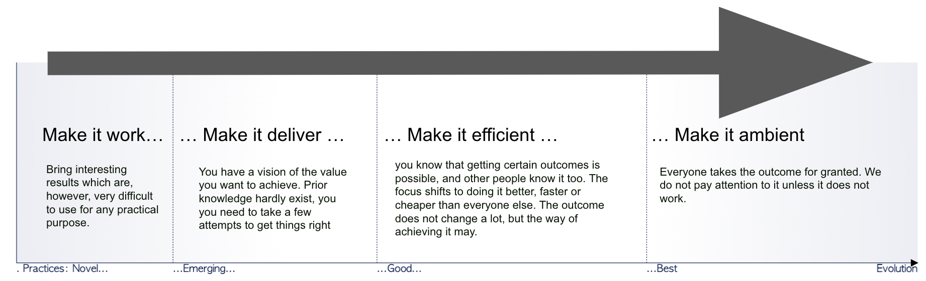
On Wardley’s evolution axis the initial article was in stage I of evolution: making it work
In this article, in a first part, we’ll explore how I effectively use the C4 tool based on CUE to organize my code, handle tags, manage versioning, and integrate with Continuous Integration and Continuous Deployment (CI/CD) systems to generate and update diagrams. We’ll also discuss the benefits of generating diagrams on push and on demand, comparing it with other tools like Mermaid.
In a second part, I will expose some considerations to use C4 at scale and expose the importance of a governance, whatever it is (sic).
Therefore, this article is about an evolution from making it efficient toward make c4 ambient.
Part I - Working in a single context: toward efficiency
Most of the time, I use the C4 model to describe a single application within a specific domain. As a result, my C1 (Context) phase is usually light and mainly focuses on the interactions between the system and end-users and external dependencies. The C2 (Container) phase provides more information, and I often use tags and sprites to combine C2 and Deployment diagrams. This is generally acceptable because my diagrams are intended to support discussions and explanations rather than being self-sufficient (they are accompanied by a narrative).
side note: you will understand why the usage of bold fonts later in the last part of this article.
Since I use the C1/C2 to support a narrative, I require different views and components depending on the message I want to convey. To organize these elements, I use a structured approach similar to coding.
Ubiquitous language: in this article I use code to represent any input from the end-user to express the diagram. It can be a Structurizr code, plantUML or CUE Data
Code Organization and Packages
To make the most of the C4 model, it’s essential to maintain a clear and logical structure in your codebase. Let’s see a practical example of what this means.
Organizing code and leveraging the lattice
Let’s start from this illustration from the original c4model.com website:
The C4 model was created as a way to help software development teams describe and communicate software architecture, both during up-front design sessions and when retrospectively documenting an existing codebase. It’s a way to create maps of your code, at various levels of detail, in the same way you would use something like Google Maps to zoom in and out of an area you are interested in.
In the context of diagram-as-code, the application of this principle can be implemented in two ways:
- by reflecting the zoom level within the code, or
- by adjusting the data at runtime to zoom on demand.
I won’t discuss the pros and cons of each method (I could write a complete article about it).
Instead, I will focus on the first option, which is the one I am using with my CUE implementation. In fact, the goal of CUE is to provide a complete description within the code, without leaving any room for data mutation at runtime, and I appreciate this philosophy.
Note, the remaining of this section is mainly about how to use the CUE4Puml4C4. Feel free so skip to the next section if you are not interested in this geeky part.
By definition, a System in my DSL is something that have a description, a label and optionnaly containers and relations.
I first define a System without the containers and relations, and instead of repeating myself, I then define another element which is the junction of the first element and the description provided.
Let’s illustrate this whith an example:
mySystemBoundaryC1: c4.#System & {
	id:          "myapp"
	label:       "My Application"
	description: "My Application is fancy"
}
mySystemBoundaryC2: c4.#System & mySystemBoundaryC1 & {
	isBoundary: true
	containers: [service1, db1]
	relations: [
		{source: service1, dest: db1, description: ""},
	]
}
service1: c4.#Container & {
	id:          "service1"
	label:       "Service 1"
	description: "Service 1 is used to apply business rules",
}
We have two data sets:
mySystemBoundaryC1, which represents an empty system, andmySystemBoundaryC2, which combinesmySystemBoundaryC1with a description of the containers and their relationships.
It’s important to note that:
mySystemBoundaryC2is not a placeholder; it is a structure that always holds the containersmySystemBoundaryC1will never have any associated containers.
However, any changes made to mySystemBoundaryC1 will be reflected in mySystemBoundaryC2.
This mechanism means that it’s not possible to override the label and descriptions of mySystemBoundaryC2 from mySystemBoundaryC1.
This is because the label cannot be both mySystemBoundaryC1.label (‘My Application’) and ‘another definition’
The DSL allows Systems to contains subsystems; actually, I often use this capability to group various elements that serves a similar purpose such as a database and its associated micro-service.
A good practice I have is to segregate the definition of the various services into packages to avoid naming collision and easy the maintenance of the global picture. Let’s now detail the rationale of the packaging system.
About packages
In this part, we’ll discuss how I leverage the notion of packages to group related code elements, making it easier to understand the overall architecture, reduce complexity, and facilitate collaboration.
Ubiquitous language: in this article, a package is a collection of related source files that are organized together within a directory. Packages provide a way to encapsulate code, which promotes reusability and modularization.
In CUE, packages are used to group related definitions, values, and constraints. CUE packages are also organized in directories, and each package has a unique name.
I inherit my directory and package layout from my experience with Go.
At the root of the project, there is the main package, that is the entrypoint that displays the global picture of the domain.
Then each subsystem is declared in its own package. I can import the C1 representation in the main model in a global C1 object, or the C2 in a global C2 object.
The resulting of this import is that the main package holds the definitions that I people entering the project needs to see in a glimpse. Later in this article we will see that this sentence is not only valuable for humans reading the README of the repo, but also for
the other systems depending on our context.
Handling Tags
Tagging is a vital aspect of C4, as it helps identify and differentiate elements within diagrams. We’ll discuss the importance of a well-defined tagging system for maintaining consistency and clarity throughout the architecture.
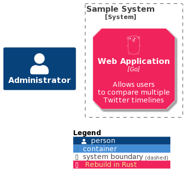
I use tags for various reasons. One of those reasons is to represent the temporal evolution of components. In simple terms, these tags act as markers to highlight any changes or transformations that will happen to the components over time. For example, you can use tags to indicate when a component is slated for removal or when it will undergo a transformation. By using these tags, you can effectively communicate the future state of the system or its components, providing a clearer understanding of the system’s life cycle and evolution.
In this case, tags are specifics and are relative to the context of the current diagram. Therefore they can be declared in the same codebase / packages.
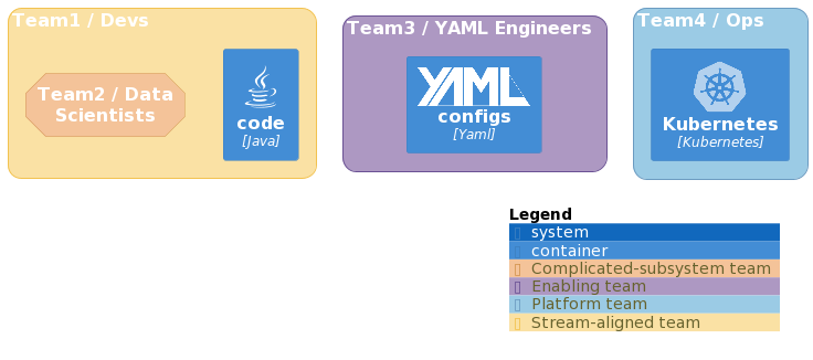
But some other elements needs tags that are standardized, therefore, a good practice is to declare them in their own package and make it available to the wild. This is an example with Team Topologies.
Applying the DevOps practices
When it comes to generating architecture diagrams, there are two main approaches: generation on push and generation on demand (such as via tools like Mermaid).
Recently, I had a discussion with a colleague and wanted to use this post to open up the discussion.
Instead of challenging the solution, let’s challenge the problem. Two fundamental elements must be considered:
- Firstly, when writing diagrams as data, the data is the reference, but in the context of C4, the goal is to get a visual representation.
- Secondly, getting a short feedback loop is essential when designing a diagram, as nobody wants to wait hours for compilation to receive feedback anymore.
Mermaid is an excellent tool for obtaining quick feedback without requiring extensive desktop tooling for the designer. It’s a JavaScript-based solution that runs in the browser out-of-the-box and is included in GitHub, making it super easy to embed diagrams in a markdown file. The drawback, however, is that the final pictures depend on both the version of the code and the version of the Mermaid toolkit.
This means that the representation may change over time, even if the code remains unchanged.
This is one of the reason which makes me prefer a generation by a CI/CD pipeline. It allows generating a static picture that consitutes the references at the time of the commit.
Another reason is that, setting a CI/CD mechanism will allow me to apply further compilation to the C4 data.
I know that some C4 tooling propose some utilities to validate the diagram against the code of the asset it represents.
As a simple conclusion to this short part, I can repeat that automation is key to maintaining up-to-date architecture diagrams.
So far, I have described some patterns I use to manage my diagrams as code. Although not strictly implemented with code, these patterns draw inspiration from software development practices.
Let’s explore how to take the management of diagrams one step further and treat them as an engineering asset. As Titus Winter once wrote
Software engineering is what happens to programming when you add time and other programmers.
By treating diagrams as engineering assets, we can optimize their management and contribute to provide the value of the C4 model at scale.
Part II - C4 at scale: making the model ambient
In the first part of this article, I used bold fonts to spot something:
Most of the time, I use the C4 model to describe a single application within a specific domain. As a result, my C1 (Context) phase is usually light and mainly focuses on the interactions between the system and end-users and external dependencies. The C2 (Container) phase provides more information, and I often use tags and sprites to combine C2 and Deployment diagrams. This is generally acceptable because my diagrams are intended to support discussions and explanations rather than being self-sufficient (they are accompanied by a narrative).
What’s important to note is that, in the context of making things more efficient, the focus is primarily on my own usage of the DSL. You make things efficient for your own purpose. An empiric consequence is that, while the DSL is a helpful tool for standardizing a model, it doesn’t necessarily ensure that every user will create diagrams using the same conventions.
A governance to rule them all
Running the C4 at scale is not only about getting a global adoption accros the various projects and products, but also about fostering a culture of shared understanding and quality in software architecture. By focusing on support, collaboration, and continuous improvement, governance can help organizations reach these goals.
About the notion of governance
Ubiquitous language: Governance, in the context of using the C4 model at scale, refers to a set of guidelines, best practices, and policies that help organizations effectively adopt and apply the C4 model across various teams and projects. The primary goal of governance in this context is to enable consistency, collaboration, and maintainability while promoting a shared understanding of software architecture.
Governance should not be viewed as a controlling or punitive measure. Instead, it should be seen as a supportive framework that empowers teams to work efficiently and effectively with the C4 model. It helps create a common language and approach for architecture discussions, increasing collaboration and enhancing the overall quality of software systems.
Some key aspects of C4 model governance might include:
- Defining and communicating standard conventions, such as naming, diagram layout, and notations, to ensure consistency and ease of understanding across teams and projects.
- Establishing best practices for creating, maintaining, and sharing C4 diagrams, including version control, documentation, and integration with other tools.
- Providing training and resources to help team members understand and effectively use the C4 model in their day-to-day work.
- Encouraging and facilitating regular reviews of software architecture, promoting a culture of continuous improvement and knowledge sharing.
- Integrating the C4 model into existing processes, such as software development life cycles, change management, and project management, to ensure that architecture considerations are an integral part of the overall development process.
- Monitoring and evaluating the effectiveness of the C4 model’s adoption within the organization, and adapting the governance framework as needed to address any challenges or opportunities for improvement.
As it is a big area and I want to stay pragmatic in this article, let’s focus on the first elements and how they can be a natural evolution of what we’ve seen so far.
Remember:
From convention to model: enforcing best practices
Conventions refer to a set of standard practices and guidelines that enable consistency and ease of understanding across various teams and projects. In the context of the C4 model, conventions can include naming conventions, diagram layout and formatting, and the use of notations to represent different elements of the architecture. Adopting standard conventions helps teams to communicate more effectively and understand each other’s work more easily.
One approach to establishing conventions for the C4 model is to develop a model of components and tags. This can help to enforce best practices for naming, labeling, and organizing the various elements of the architecture. For example, the model could include standardized names for different types of components, such as databases, servers, and services, as well as tags to indicate the role, status, or priority of each component.
Using a model of components and tags can help to ensure consistency and promote best practices across teams and projects. It can also make it easier to integrate the C4 model into existing processes and tools, such as project management software or version control systems.
An illustration of such a principle was evoked in the previous part:
- We used the model documented by Team Topologies, which provides a set of standard practices and guidelines for organizing and communicating about team structures and interactions.
- We also standardized the representation of architecture diagrams by making a set of tags available to everyone. This helped to ensure consistency and ease of understanding across teams and projects.
By adopting these principles, we can help to establish a common language and approach for software architecture that promotes collaboration, consistency, and maintainability.
However, it’s important to note that conventions should not be seen as rigid rules that must be followed at all costs. Rather, they should be flexible enough to allow for variation and experimentation while still maintaining a consistent approach to architecture. Regular reviews and feedback can help to ensure that conventions are effective and relevant, and can be adapted as needed over time.
This is why they should be an implementation of the governance principles that should be handled as code as well.
My personal opinion is that a federated governance (like the one governing the web) is more an enabler to such practices.
Conclusion and next steps
The C4 model offers a powerful way to visualize software architecture, but harnessing its full potential requires careful organization, tagging, versioning, and automation.
By implementing these strategies and understanding the benefits, you’ll be well-equipped to create clear, consistent, and up-to-date representations of your software systems that facilitate collaboration and understanding among stakeholders.
Seeking efficiency in a diagramin model, extracting best practices can leverage the power of the C4 model at scale.
Dealing with diagram as code also offers new perspectives that goes beyond the visual representation. We’ve evoked the notion of coherence between the architecture and the code of an asset. Some people colleagues told me that they were experimenting cost optimization by analysing the interaction of the various services thanks to the global C1/C2 view of their assets.
edit you can comment this article on linkedin if you want.